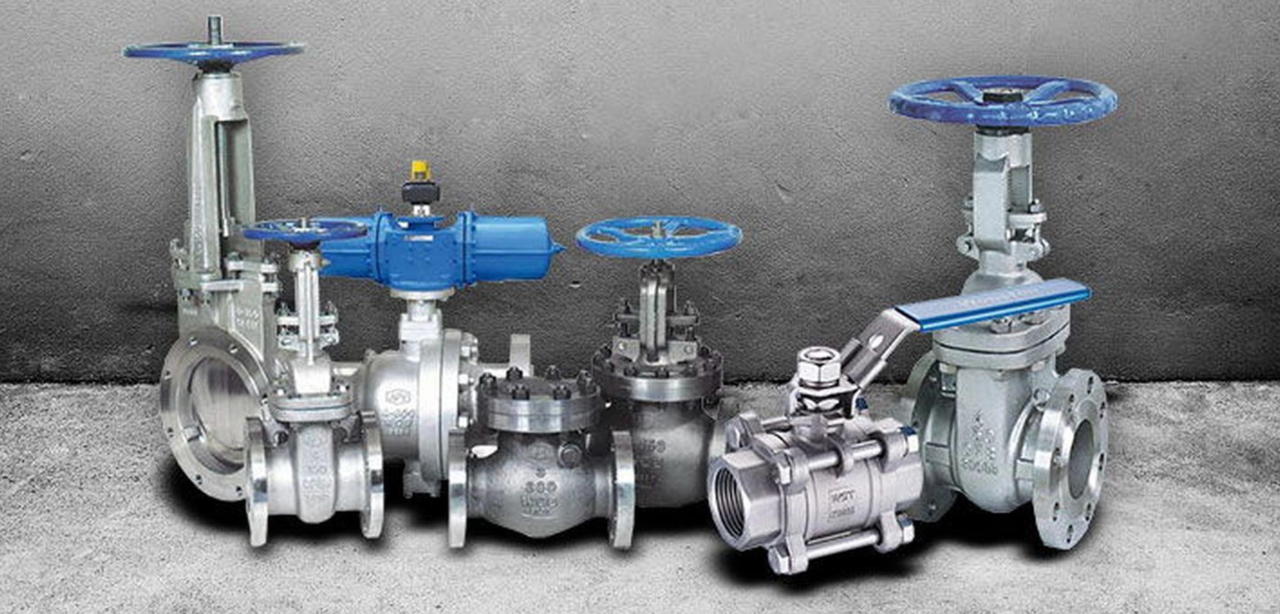
Industrial Valves
A valve is a device that regulates the flow of gases, liquids or loose materials through an aperture, such as a pipe, by opening, closing or obstructing a port or passageway.
3 basics functions of valves: on/off, volume & directional
Isolating service:
Used in on/off service, isolating valves can sometimes be called block valves. They are designed to operate in either full open or full closed position, just like light switches are used to turn lights on or off. In critical applications these valves are often motor-operated. The most common type of isolating valve is the gate valve, but other types have made an advance, especially over the past 30 years.
Controlling and regulating:
Control valves are usually globe, ball, butterfly, or plug types and are used to regulate the flow in a line. They are designed to operate in the “less-than-full-open” position. The oldest and still most popular regulating valve design is globe. Gate valves should never be used for throttling or regulating unless the flow velocity is very low. High velocity flow in a gate valve used for regulating can quickly destroy the seating surfaces and result in leakage when fully closed. For effective flow regulation, the flow rate should be proportional to the amount of closure of the stem. However, certain control applications do not need to meet such requirement, such as a quick opening response. The most accurate and reliable flow control is performed by control or regulating valves operated by a controller and an actuator, rather than by manual operation.
Check or non-return:
Check and non-return valves only allow flow in one direction and block the flow from returning in the opposite direction, as can be shown in picture on the left. Check valves are the “one-way-street controllers” of the valve industry. They are marked with a flow arrow on the exterior surface to ensure they are installed in the proper orientation. Check valves protect many pieces of process equipment including pumps, turbines and boilers. Except if these valves are equipped with soft, elastomer seating inserts, they will leak to some degree. Therefore, unless soft-seated, check valves should not be counted on for absolute shut-off.
Valve market segments:
The entire valve industry is very broad shouldered, with very diverse segments that feature valve products that are often totally different from one another. Here is a list of major market segments:
Water and wastewater Home plumbing systems
Heating, ventilating & air-conditioning (HVAC)
Fire protection
Power generation
Refining, petrochemical and chemical
Various upstream & midstream applications
| STANDARD SPECIFICATION |
API 6D,API 598,API 600, API 603,API 602, ASME B 16.34, ASME ANSI B16.10, ASME ANSI B16.5,ASME ANSI B16.25, |
|---|---|
| SIZE RANGE | BUTTWELD-2”-24” FORGED-1/2”-2” |
| PRESSURE RATING | BUTTWELD-150#-2500# FORGED-1500#-4500# |
| MOC | STAINLESS STEEL, CAST IRON, CARBON STEEL, MILD STEEL, DUCTILE IRON |
| END TYPE | FLANGE END,THREADED END,BUTTWELD END |
| TYPES | ACTUATOR,SOLENOID |
Gate Valve
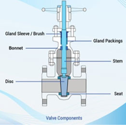
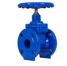
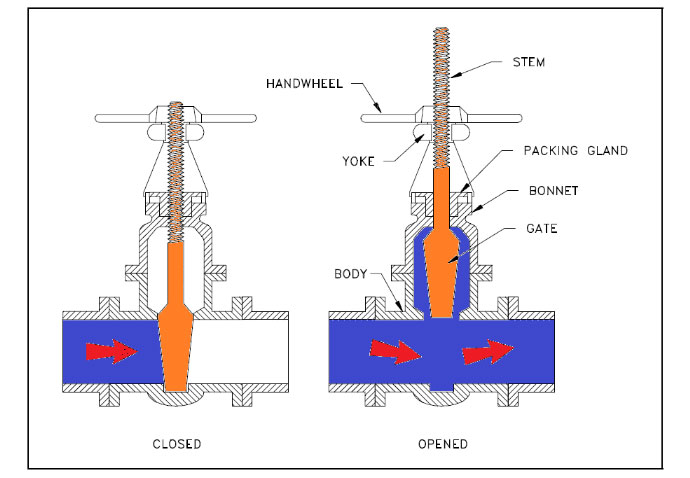
The gate valve is perhaps the most frequently used valve in piping systems. It is a general service valve that is used primarily for on-off, nonthrottling applications. When fully opened, the gate valve creates minimal obstruction to the flow. With less obstruction to the commodity’s rate of flow through the valve’s body, there is less turbulence, resulting in minimal drop in commodity pressure. Gate valves control the commodity flowing through the pipe with a flat, vertical wedge, or gate, that slides up or down as the valve’s handwheel is turned. As the handwheel is rotated, the wedge will slide through the valve body to block or release the flow.
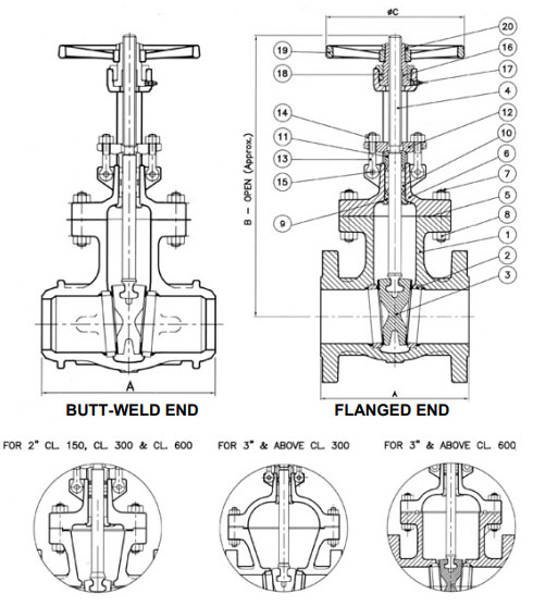
| Valve Size | Class 150 | Class 300 | Class 600 | |||||||||||||||
|---|---|---|---|---|---|---|---|---|---|---|---|---|---|---|---|---|---|---|
| A | B | C | Approx. Wt. | A | B | C | Approx. Wt. | A | B | C | Approx. Wt. | |||||||
| FT | B.W | FT | B.W | FT | B.W | FT | B.W | FT | B.W | FT | B.W | |||||||
| 50 (2") | 178 | 216 | 376 | 203 | 21 | 19 | 216 | 216 | 399 | 203 | 25 | 23 | 292 | 292 | 399 | 203 | 42 | 36 |
| 65 (21/2") | 191 | 241 | 480 | 229 | 32 | 27 | 241 | 241 | 505 | 229 | 48 | 34 | - | - | - | - | - | |
| 80 (3") | 203 | 283 | 480 | 229 | 35 | 27 | 283 | 283 | 505 | 229 | 53 | 41 | 356 | 356 | 541 | 254 | 67 | 63 |
| 100 (4") | 229 | 305 | 584 | 254 | 53 | 43 | 305 | 305 | 604 | 254 | 78 | 55 | 432 | 432 | 635 | 305 | 119 | 112 |
| 125 (5") | 254 | 381 | 750 | 254 | 75 | 64 | 381 | 381 | 850 | 356 | 135 | 105 | - | - | - | - | - | |
| 150 (6") | 267 | 403 | 790 | 305 | 87 | 77 | 403 | 403 | 850 | 356 | 158 | 111 | 559 | 559 | 874 | 457 | 252 | 225 |
| 200 (8") | 292 | 419 | 996 | 356 | 139 | 118 | 419 | 419 | 1039 | 406 | 234 | 186 | 660 | 660 | 1044 | 457 | 418 | 365 |
| 250 (10") | 330 | 457 | 1205 | 406 | 210 | 198 | 457 | 457 | 1265 | 457 | 355 | 284 | 787 | 787 | 1285 | 508 | 652 | 554 |
| 300 (12") | 356 | 502 | 1410 | 457 | 302 | 271 | 502 | 502 | 1460 | 508 | 495 | 400 | 838 | 838 | 1476 | 610 | 1100 | 984 |
| 350 (14") | 381 | 572 | 1539 | 508 | 410 | 365 | 762 | 762 | 1590 | 508 | 750 | 620 | 889 | 889 | 1565 | 610 | 1600 | 1465 |
| 400 (16") | 406 | 610 | 1752 | 508 | 520 | 490 | 838 | 838 | 1791 | 610 | 958 | 850 | 991 | 991 | 2062 | 762 | 1955 | 1760 |
| 450 (18") | 432 | 660 | 1956 | 610 | 690 | 665 | 914 | 914 | 2126 | 686 | 1310 | 1075 | 1092 | 1092 | 2062 | 762 | 2075 | 1840 |
| 500 (20") | 457 | 711 | 2159 | 610 | 900 | 865 | 991 | 991 | 2261 | 686 | 1640 | 1525 | 1194 | 1194 | 3048 | 762 | 2150 | 1960 |
| 600 (24") | 508 | 813 | 2565 | 686 | 1410 | 1375 | 1143 | 1143 | 2654 | 762 | 2460 | 2075 | 1397 | 1397 | 3150 | 762 | 3620 | 3180 |
Globe Valve
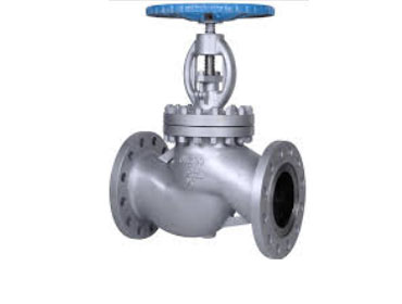
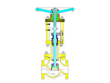
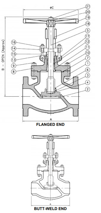
What Is A Globe Valve?
A globe valve is an instrument used to stop and/or control the flow of fluids in a pipeline. It
works by halting the flow of a fluid through a pipe. The name globe comes about due to the
valve’s cylindrical shape. There are usually two halves of the body within the globe valve
that are separated by an internal baffle.
Even though globe valves exhibit more pressure drops than gate valves, you can use them
where the pressure drop via the valve is a non-controlling factor. Another name for globe
valves is throttle valves when they are used for throttling purposes.
| Valve Size | Class 150 | Class 300 | Class 600 | |||||||||||||||
|---|---|---|---|---|---|---|---|---|---|---|---|---|---|---|---|---|---|---|
| A | B | C | Approx. Wt. | A | B | C | Approx. Wt. | A | B | C | Approx. Wt. | |||||||
| FT | B.W | FT | B.W | FT | B.W | FT | B.W | FT | B.W | FT | B.W | |||||||
| 50 (2") | 203 | 203 | 335 | 203 | 23 | 20 | 267 | 267 | 355 | 203 | 33 | 28 | 292 | 292 | 400 | 254 | 42 | 38 |
| 65 (21/2") | 216 | - | 355 | 203 | 35 | - | 292 | - | 410 | 203 | 46 | - | - | - | - | - | - | - |
| 80 (3") | 242 | 242 | 421 | 254 | 41 | 38 | 317 | 317 | 457 | 254 | 58 | 50 | 356 | 356 | 560 | 356 | 75 | 60 |
| 100 (4") | 292 | 292 | 477 | 254 | 66 | 62 | 356 | 356 | 556 | 356 | 97 | 84 | 432 | 432 | 593 | 406 | 136 | 116 |
| 150 (6") | 406 | 406 | 575 | 356 | 118 | 110 | 445 | 445 | 668 | 457 | 186 | 164 | 559 | 559 | 837 | 610 | 245 | 195 |
| 200 (8") | 495 | 495 | 680 | 457 | 207 | 195 | 559 | 559 | 830 | 610 | 329 | 296 | 661 | 661 | 947 | 610 | 546 | 466 |
| 250 (10") | 623 | 623 | 895 | 356 | 335 | 320 | 623 | 623 | 1206 | 610 | 520 | 471 | 787 | 787 | 1285 | 762 | 756 | 656 |
| 300 (12") | 699 | 699 | 1215 | 610 | 495 | 470 | 711 | 711 | 1160 | 762 | 705 | 634 | 838 | 838 | 1560 | 762 | 1086 | 896 |
Butterfly Valve
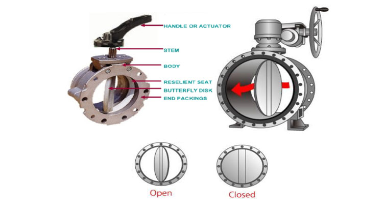
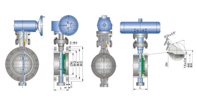
A butterfly valve is from a family of valves called quarter-turn valves. In operation, the valve is fully open or closed when the disc is rotated a quarter turn. The "butterfly" is a metal disc mounted on a rod. When the valve is closed, the disc is turned so that it completely blocks off the passageway. When the valve is fully open, the disc is rotated a quarter turn so that it allows an almost unrestricted passage of the fluid. The valve may also be opened incrementally to throttle flow. There are different kinds of butterfly valves, each adapted for different pressures and different usage. The zero-offset butterfly valve, which uses the flexibility of rubber, has the lowest pressure rating. The high-performance double offset butterfly valve, used in slightly higher-pressure systems, is offset from the center line of the disc seat and body seal (offset one), and the center line of the bore (offset two). This creates a cam action during operation to lift the seat out of the seal resulting in less friction than is created in the zero offset design and decreases its tendency to wear. The valve best suited for high-pressure systems is the triple offset butterfly valve. In this valve, the disc seat contact axis is offset, which acts to virtually eliminate sliding contact between disc and seat. In the case of triple offset valves the seat is made of metal so that it can be machined such as to achieve a bubble-tight shut-off when in contact with the disc.
FLANGED & BW TRIPLE OFFSET BUTTERFLY VALVE DIMENSIONS FOR CLASS 150LBS:
| Size | Dimensions(mm) | |||||||||||
| L | ||||||||||||
| Class | NPS | DN | RF | BW | D | G | f | K | Z-O | C | A | B |
| 2 | 50 | 108 | 150 | 152 | 91.9 | 1.6 | 120.7 | 4-19.1 | 15.8 | 63 | ||
| 21/2 | 65 | 112 | 170 | 178 | 104.6 | 1.6 | 139.7 | 4-19.1 | 17.5 | 75 | ||
| 3 | 80 | 114 | 180 | 191 | 127 | 1.6 | 152.4 | 4-19.1 | 19.1 | 91 | ||
| 4 | 100 | 127 | 190 | 229 | 157.2 | 1.6 | 190.5 | 8-19.1 | 23.9 | 117 | ||
| 5 | 125 | 140 | 200 | 254 | 185.7 | 1.6 | 215.9 | 8-22.2 | 23.9 | 144 | ||
| 6 | 150 | 140 | 210 | 279 | 215.9 | 1.6 | 241.3 | 8-22.2 | 25.4 | 172 | ||
| 8 | 200 | 152 | 230 | 343 | 269.7 | 1.6 | 298.5 | 8-22.2 | 28.4 | 223 | ||
| 10 | 250 | 165/203 | 250 | 406 | 323.9 | 1.6 | 362 | 12-25.4 | 30.2 | 278 | ||
| 12 | 300 | 178/203 | 270 | 483 | 381 | 1.6 | 431.8 | 12-25.4 | 31.8 | 329 | ||
| 14 | 350 | 190 | 290 | 533 | 412.8 | 1.6 | 476.2 | 12-28.6 | 35.1 | 362 | ||
| 16 | 400 | 216 | 310 | 597 | 469.9 | 1.6 | 539.8 | 16-28.6 | 36.6 | 413 | ||
| 18 | 450 | 222 | 330 | 635 | 533.4 | 1.6 | 577.9 | 16-31.8 | 39.6 | 464 | ||
| 20 | 500 | 229 | 350 | 699 | 584.2 | 1.6 | 635 | 20-31.8 | 42.9 | 516 | ||
| 150Lb | 24 | 600 | 267 | 390 | 813 | 692.2 | 1.6 | 749.3 | 20-34.9 | 47.8 | 619 | |
| 26 | 650 | 292 | 410 | 786 | 711.2 | 1.6 | 744.5 | 36-22.2 | 41.1 | 670 | ||
| 28 | 700 | 292 | 430 | 837 | 762 | 1.6 | 795.3 | 40-22.2 | 44.5 | 721 | ||
| 30 | 750 | 318 | 450 | 887 | 812.8 | 1.6 | 846.1 | 44-22.2 | 44.5 | 772 | ||
| 32 | 800 | 318 | 470 | 941 | 863.6 | 1.6 | 900.2 | 48-22.2 | 46 | 825 | ||
| 36 | 900 | 330 | 510 | 1057 | 971.6 | 1.6 | 1009.7 | 44-25.4 | 52.3 | 927 | ||
| 38 | 950 | 410 | 530 | 1124 | 1022.4 | 1.6 | 1069.8 | 40-28.6 | 53.8 | 978 | ||
| 40 | 1000 | 410 | 550 | 1175 | 1079.5 | 1.6 | 1120.6 | 44-28.6 | 55.6 | 1029 | ||
| 42 | 1050 | 410 | 570 | 1226 | 1130.3 | 1.6 | 1171.4 | 48-28.6 | 58.7 | 1080 | ||
| 44 | 1100 | 444 | 570 | 1276 | 1181.1 | 1.6 | 1222.2 | 52-28.6 | 60.5 | 1130 | ||
| 48 | 1200 | 470 | 630 | 1392 | 1289.1 | 1.6 | 1335 | 44-31.8 | 65 | 1232 | ||
| 52 | 1300 | 470 | 630 | 1494 | 1390.7 | 1.6 | 1436.6 | 52-31.8 | 69.9 | 1334 | ||
| 56 | 1400 | 530 | 710 | 1600 | 1492.3 | 1.6 | 1543.1 | 60-31.8 | 73.2 | 1436 | ||
| 60 | 1500 | 530 | 710 | 1726 | 1600.2 | 1.6 | 1662.2 | 52-34.9 | 76.2 | 1538 | ||
Ball Valve
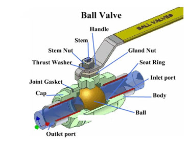
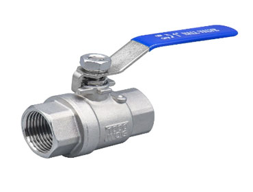
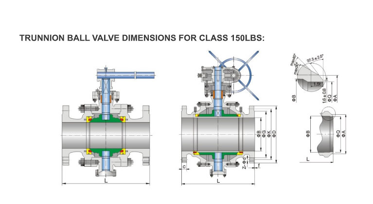
A ball valve is a form of quarter-turn valve that uses a pivoting ball that has been drilled through to control flow. When the hole is in line with the flow direction, it allows fluids or gasses to pass through. Alternatively, when the ball is turned 90 degrees, the flow is stopped completely. In either case, the handle serves as a visual indicator of the valve’s status. If the handle is parallel to the valve, it's open. In contrast, if the handle is perpendicular, the valve is closed. Ball valves are incredibly robust valves and great for applications where a simple on/off action is needed. They're durable and maintain their ability to perform consistently after many cycles. Additionally, they have excellent reliability and close securely even after long periods of disuse. Flow rate can also be controlled by partially opening or closing the valve to various degrees. These qualities make them an excellent choice for shutoff and control applications over gate and globe style valves.
| Size | Dimensions(mm) | |||||||||||||
| L | ||||||||||||||
| Class | NPS | DN | RF | BW | B | D | G | f | K | Z-od | C | A | Q | |
| 2 | 50 | 178 | 216 | 49 | 152 | 91.9 | 1.6 | 120.7 | 4-19.1 | 15.8 | 63 | |||
| 21/2 | 65 | 191 | 241 | 62 | 178 | 104.6 | 1.6 | 139.7 | 4-19.1 | 17.5 | 75 | |||
| 3 | 80 | 203 | 283 | 74 | 191 | 127 | 1.6 | 152.4 | 4-19.1 | 19.1 | 91 | |||
| 4 | 100 | 229 | 305 | 100 | 229 | 157.2 | 1.6 | 190.5 | 8-19.1 | 23.9 | 117 | |||
| 6 | 150 | 394 | 457 | 150 | 279 | 215.9 | 1.6 | 241.3 | 8-22.2 | 25.4 | 172 | |||
| 8 | 200 | 457 | 521 | 201 | 343 | 269.7 | 1.6 | 298.5 | 8-22.2 | 28.4 | 223 | |||
| 10 | 250 | 533 | 559 | 252 | 406 | 323.9 | 1.6 | 362 | 12-25.4 | 30.2 | 278 | |||
| 12 | 300 | 610 | 635 | 303 | 483 | 381 | 1.6 | 431.8 | 12-25.4 | 31.8 | 329 | As per | ||
| 14 | 350 | 686 | 762 | 334 | 533 | 412.8 | 1.6 | 476.2 | 12-28.6 | 35.1 | 362 | client's | ||
| 150Lb | 16 | 400 | 762 | 838 | 385 | 597 | 469.9 | 1.6 | 539.8 | 16-28.6 | 36.6 | 413 | ||
| 18 | 450 | 864 | 914 | 436 | 635 | 533.4 | 1.6 | 577.9 | 16-31.8 | 39.6 | 464 | |||
| 20 | 500 | 914 | 991 | 487 | 699 | 584.2 | 1.6 | 635 | 20-31.8 | 42.9 | 516 | |||
| 24 | 600 | 1067 | 1143 | 589 | 813 | 692.2 | 1.6 | 749.3 | 20-34.9 | 47.8 | 619 | |||
| 26 | 650 | 1143 | 1245 | 633 | 870 | 749.3 | 1.6 | 806.5 | 24-34.9 | 68.3 | 670 | |||
| 28 | 700 | 1245 | 1346 | 684 | 927 | 800.1 | 1.6 | 863.6 | 28-34.9 | 71.4 | 721 | |||
| 30 | 750 | 1295 | 1397 | 735 | 984 | 857.3 | 1.6 | 914.4 | 28-34.9 | 74.7 | 772 | |||
| 32 | 800 | 1372 | 1524 | 779 | 1060 | 914.4 | 1.6 | 977.9 | 28-41.3 | 80.8 | 825 | |||
| 34 | 850 | 1473 | 1626 | 830 | 1111 | 965.2 | 1.6 | 1028.7 | 32-41.3 | 82.6 | 876 | |||
| 36 | 900 | 1524 | 1727 | 874 | 1168 | 1022.4 | 1.6 | 1085.9 | 32-41.3 | 90.4 | 927 | |||
Swing Check Valve
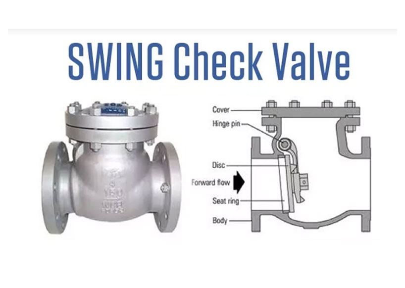
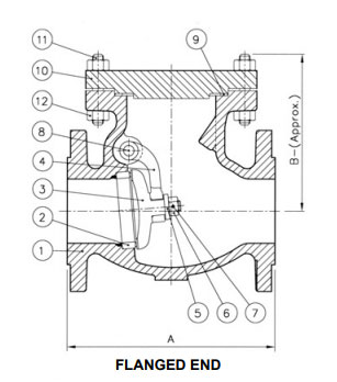
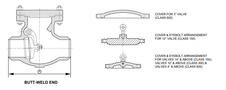
A swing check valve (or tilting disc check valve) is a check valve in which the disc, the movable part to block the flow, swings on a hinge or trunnion, either onto the seat to block reverse flow or off the seat to allow forward flow. The seat opening cross-section may be perpendicular to the centerline between the two ports or at an angle. Although swing check valves can come in various sizes, large check valves are often swing check valves.
| Valve Size | Class 150 | Class 300 | Class 600 | |||||||||||||||
|---|---|---|---|---|---|---|---|---|---|---|---|---|---|---|---|---|---|---|
| A | B | Approx. Wt. | A | B | Approx. Wt. | A | B | Approx. Wt. | ||||||||||
| FT | B.W | FT | B.W | FT | B.W | FT | B.W | FT | B.W | FT | B.W | |||||||
| 50 (2") | 203 | 203 | 165 | 21 | 19 | 267 | 267 | 165 | 24 | 19 | 292 | 292 | 178 | 35 | 30 | |||
| 65 (21/2") | 216 | 216 | 175 | 24 | 20 | - | - | - | - | - | - | - | - | - | - | |||
| 80 (3") | 241 | 241 | 181 | 34 | 30 | 317 | 317 | 190 | 45 | 36 | 356 | 356 | 203 | 55 | 46 | |||
| 100 (4") | 292 | 292 | 213 | 49 | 42 | 356 | 356 | 229 | 70 | 56 | 432 | 432 | 229 | 92 | 70 | |||
| 150 (6") | 356 | 356 | 273 | 88 | 79 | 444 | 444 | 279 | 151 | 129 | 559 | 559 | 365 | 204 | 161 | |||
| 200 (8") | 495 | 495 | 335 | 168 | 154 | 533 | 533 | 343 | 242 | 210 | 661 | 661 | 442 | 323 | 260 | |||
| 250 (10") | 622 | 622 | 406 | 280 | 260 | 622 | 622 | 368 | 333 | 284 | 787 | 787 | 450 | 550 | 455 | |||
| 300 (12") | 698 | 698 | 483 | 413 | 382 | 711 | 711 | 412 | 450 | 378 | 838 | 838 | 590 | 790 | 680 | |||
| 350 (14") | 788 | 788 | 515 | 509 | 466 | 839 | 839 | 559 | 659 | 556 | - | - | - | - | - | |||
| 400 (16") | 864 | 864 | 455 | 580 | 524 | 864 | 864 | 636 | 873 | 747 | - | - | - | - | - | |||
| 450 (18") | 978 | 978 | 500 | 635 | 583 | 978 | 978 | 562 | 1090 | 900 | - | - | - | - | - | |||
| 500 (20") | 978 | 978 | 675 | 925 | 855 | 1016 | 1016 | 675 | 1360 | 1176 | - | - | - | - | - | |||
| 600 (24") | 1295 | 1295 | 780 | 1500 | 1403 | 1346 | 1346 | 790 | 1850 | 1573 | - | - | - | - | - | |||
Needle Valve
A needle valve is a type of valve with a small port and a threaded, needle-shaped plunger. It allows precise regulation of flow, although it is generally only capable of relatively low flow rates. Needle valves are usually used in flow-metering applications, especially when a constant, calibrated, low flow rate must be maintained for some time, such as the idle fuel flow in a carburettor.
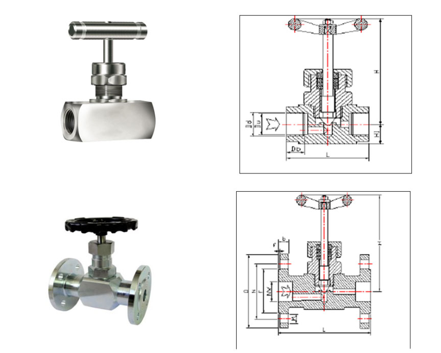
| PN 0-250 Kg/cm2 THREADED NEEDLE VALVE (Di$Li) | |||||||
| FULL BORE DIMENSIONS | |||||||
| INCH | MM | L | H | H1 | Du | Dd | Db |
| 1/2" | 15 | 75 | 130 | 20 | 18.63 | 20.96 | 14 |
| 3/4" | 20 | 85 | 140 | 25 | 24.12 | 26.44 | 14 |
| 1" | 25 | 100 | 150 | 28 | 30.29 | 33.25 | 21 |
| 11/4" | 32 | 110 | 160 | 30 | 38.95 | 41.91 | 25 |
| 11/2" | 40 | 125 | 175 | 32 | 44.85 | 47.81 | 25 |
| 2" | 50 | 145 | 185 | 38 | 56.66 | 59.62 | 28.5 |
| PN 0-250 Kg/cm2 THREADED NEEDLE VALVE (Di$Li) | ||||||||||
| FULL BORE DIMENSIONS | ||||||||||
| INCH | MM | L | H | D | N | F | b | f | M | Z |
| 1/2" | 15 | 130 | 130 | 95 | 65 | 45 | 16 | 2 | 14 | 4 |
| 3/4" | 20 | 150 | 140 | 105 | 75 | 58 | 18 | 2 | 14 | 4 |
| 1" | 25 | 160 | 150 | 115 | 85 | 68 | 18 | 2 | 14 | 4 |
| 11/4" | 32 | 180 | 160 | 140 | 100 | 78 | 18 | 2 | 14 | 4 |
| 11/2" | 40 | 200 | 175 | 150 | 110 | 88 | 18 | 3 | 18 | 4 |
| 2" | 50 | 230 | 185 | 165 | 125 | 102 | 20 | 3 | 18 | 4 |
Safety Relief Valve
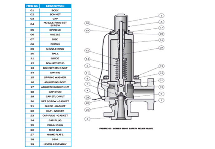
A relief valve or pressure relief valve (PRV) is a type of safety valve used to control or limit
the pressure in a system; excessive pressure might otherwise build up and create a process
upset, instrument or equipment failure, explosion, or fire.
STANDARD FOR SAFETY VALVES- SAA AS1271, EN ISO 4126, AD-Merkblatt A2, TRD 421, TRD
721, JIS B 8210, ASME I , ASME III , ASME VIII, ANSI/ASME
PTC 25.3, API RP 520, API RP 521, API STD 526, API STD 527.
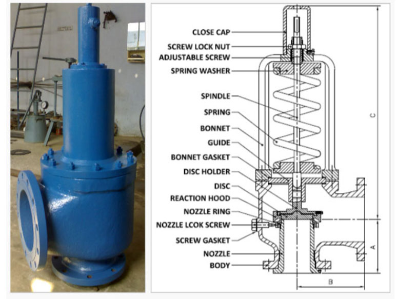
| Valve Size | Orifice Code | Orifice Diameter (MM) | Dimensions | ||
| A | B | C | |||
| 25 x 50 | D | 9.5 | 105.0 | 114.5 | 440 |
| 25 x 50 | E | 12.5 | 105.0 | 114.5 | 440 |
| 25 x 50 | G | 23.0 | 105.0 | 114.5 | 440 |
| 40 x 50 | F | 16.0 | 124.0 | 120.5 | 500 |
| 40 x 65 | G | 23.0 | 124.0 | 120.5 | 500 |
| 40 x 80 | H | 28.0 | 130.0 | 124.0 | 525 |
| 40 x 80 | J | 31.5 | 130.0 | 124.0 | 575 |
| 50 x 80 | H | 28.0 | 133.0 | 124.0 | 525 |
| 50 x 80 | J | 32.5 | 133.0 | 124.0 | 575 |
| 50 x 80 | K | 36.5 | 133.0 | 124.0 | 575 |
| 65 x 100 | J | 32.5 | 136.0 | 143.0 | 600 |
| 80 x 100 | K | 42.5 | 155.0 | 162.0 | 615 |
| 80 x 100 | L | 50.0 | 155.0 | 162.0 | 615 |
| 80 x 100 | M | 56.0 | 155.0 | 162.0 | 615 |
| 100 x 150 | P | 72.5 | 181.0 | 229.0 | 890 |
| 100 x 150 | Q | 95.5 | 181.0 | 229.0 | 890 |
| 150 x 200 | Q | 95.5 | 240.0 | 241.0 | 1150 |
| 150 x 200 | R | 115.0 | 240.0 | 241.0 | 1150 |
Safety Valve also known by the name of Pressure Relief Valve (PRV) and Pressure Safety Valve (PSV).
Other names of Safety Valves are Safety Relief Valve, Thermal Relief Valve, Relief Valve, Spring Loaded
Safety Valve, Angle Type Safety Valve, Pilot Operated Safety Relief Valve and Low Pressure Safety Relief
Valve.
The difference in between Pressure Safety Valve (PSV) and Pressure Relief Valve is Pressure Safety Relief
Valve have provided a manual lever with a cap to relieve the pressure in case of emergency.
Mostly two types of protection encountered in Industries which are Flow Protection & Thermal Protection.
Flow protection is done by the using of Safety Relief Valves and Thermal Protection by Thermal Relief
Valve.