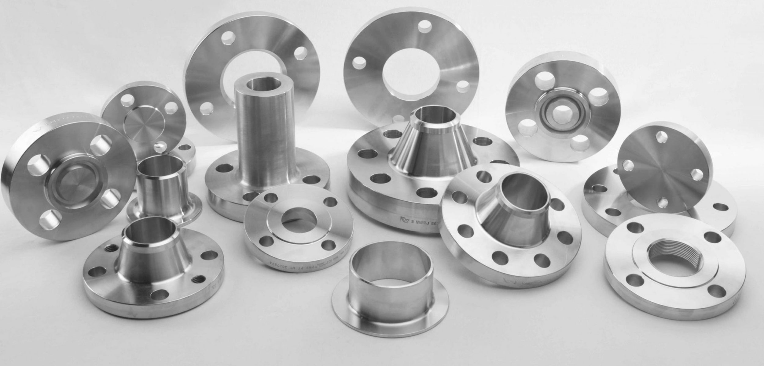
Flanges
A flange is an externally or internally protruding ridge, lip, or rim that has several uses: it can be used to transfer contact force easily to another object (like the flange on a steam cylinder, pipe, or camera lens mount); it can increase strength (like the inside flange of a rail car or tram wheel that prevents the wheels from running off the rails); or it can stabilize and guide the movements of a machine or its parts. Bolts installed in the shape of a bolt circle are frequently used to secure flanges. Flanges are essential components of pipe systems because they make maintenance, inspection, and modification simple.They make it possible to join or separate pipes and equipment without the need for welding, which makes installation easier and cuts down on downtime for maintenance or upgrades. Flanges also make it easier for pipes to align, guaranteeing a good fit and reducing system stress.
Flange Specification
| Standard: |
ASTM A182, BS 10, MSS SP44, ASA, API-605 JIS 2K,5K,10K,16K,20K,30K,40K,63K |
| Pressure Rating: |
150# To 2500# (PN2.5 ,PN6 , PN10 , PN16 , PN25 , PN40 ,PN64 , PN100) |
| Flange Face Type: | Flate Face (FF), Raised Face (RF), Ring Type Joint (RTJ) |
| Coating/Surface Treatment: | Anti-rust Paint, Oil Black Paint, Yellow Transparent, Zinc Plated, Cold and Hot Dip Galvanized |
| Value Added Services: | CNC Machining, Customised Flanges Sizes for Slip On Flanges All Slip On Flanges are available in sizes from 1/4 TO 48". |
| Material Type | Common Grades | Applications |
|---|---|---|
| Stainless Steel | 304 ,304L,304H ,309 ,310S, 316 ,316L , 316Ti, 317L,321, 347, 904L | Chemical processing, food and beverage, pharmaceuticals, oil and gas, water treatment |
| 409, 410, 410S, 420, 420F, 430, 431, 440A, 440B, 440C, 446, 17-4 PH, 17-7 PH | Chemical processing & oil & gas industry | |
| 904L | Marine and Offshore | |
| Alloy Steel | ASTM A182 F5, F9, F11, F22, F91 | Power generation, oil and gas, petrochemicals |
| Duplex & Super Duplex | UNS S31803 (Duplex), UNS S32750 (Super Duplex), UNS S32760 (Super Duplex) | Desalination plants, chemical processing, offshore and marine applications, oil and gas extraction |
| Nickel Alloy | ASTM B564, B649, B462, B151 | Aerospace, marine, chemical processing, oil and gas, nuclear |
| Carbon Steel | ASTM A105 | Petrochemicals, power generation, gas processing |
| Mild Steel | ASME B16.5 | General construction, structural components |
Weld Neck Flange
Weld Neck Flange is flanges that designed to be joined to a piping system by butt welding. This kind of flange include lots of specification. Weld Neck Flange is expensive because of its long neck and cost of people for contact WN flange with pipeline or fitting but is preferred for high-stress applications. The necks, or hubs, transmits stresses to the pipeline. The gradual transition of thickness from the base of the hub to the wall thickness at the butt weld provides important reinforcement of the Weld Neck Flange. The bore of Weld-Neck flange matches bore of the pipeline, reducing turbulence and erosion.
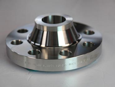
| ANSI, ASME, ASA, B16.5 150lb/sq.in. WELDING NECK FLANGE RF | |||||||||||
| ø | D | b | g | m | a | J* | h | k | Holes | l | Kg. |
| 1/2" | 88,9 | 11,1 | 34,9 | 30,2 | 21,3 | 15,7 | 47,6 | 60,3 | 4 | 15,9 | 0,500 |
| 3/4" | 98,4 | 12,7 | 42,9 | 38,1 | 26,7 | 20,8 | 52,4 | 69,8 | 4 | 15,9 | 0,700 |
| 1" | 107,9 | 14,3 | 50,8 | 49,2 | 33,5 | 26,7 | 55,6 | 79,4 | 4 | 15,9 | 1,100 |
| 1 1/4" | 117,5 | 15,9 | 63,5 | 58,8 | 42,2 | 35,1 | 57,1 | 88,9 | 4 | 15,9 | 1,500 |
| 1 1/2" | 127,0 | 17,5 | 73,0 | 65,1 | 48,3 | 40,9 | 61,9 | 98,4 | 4 | 15,9 | 1,800 |
| 2" | 152,4 | 19,0 | 92,1 | 77,8 | 60,3 | 52,6 | 63,5 | 120,6 | 4 | 19,0 | 2,700 |
| 2 1/2" | 177,8 | 22,2 | 104,8 | 90,5 | 73,1 | 62,7 | 69,8 | 139,7 | 4 | 19,0 | 4,400 |
| 3" | 190,5 | 23,8 | 127,0 | 107,9 | 88,9 | 78,0 | 69,8 | 152,4 | 4 | 19,0 | 5,200 |
| 3 1/2" | 215,9 | 23,8 | 139,7 | 122,2 | 101,6 | 90,2 | 71,4 | 177,8 | 8 | 19,0 | 6,400 |
| 4" | 228,6 | 23,8 | 157,2 | 134,9 | 114,3 | 102,4 | 76,2 | 190,5 | 8 | 19,0 | 7,500 |
| 5" | 254,0 | 23,8 | 185,7 | 163,5 | 141,2 | 128,3 | 88,9 | 215,9 | 8 | 22,2 | 9,200 |
| 6" | 279,4 | 25,4 | 215,9 | 192,1 | 168,4 | 154,2 | 88,9 | 241,3 | 8 | 22,2 | 11,000 |
| 8" | 342,9 | 28,6 | 269,9 | 246,1 | 219,1 | 202,7 | 101,6 | 298,4 | 8 | 22,2 | 18,300 |
| 10" | 406,4 | 30,2 | 323,8 | 304,8 | 273,0 | 254,5 | 101,6 | 361,9 | 12 | 25,4 | 25,000 |
| 12" | 482,6 | 31,7 | 381,0 | 365,1 | 323,8 | 304,8 | 114,3 | 431,8 | 12 | 25,4 | 39,000 |
| 14" | 533,4 | 34,9 | 412,7 | 400,0 | 355,6 | 336,5 | 127,0 | 476,2 | 12 | 28,6 | 51,000 |
| 16" | 596,9 | 36,5 | 469,9 | 457,2 | 406,4 | 387,3 | 127,0 | 539,7 | 16 | 28,6 | 60,000 |
| 18" | 635,0 | 39,7 | 533,4 | 504,8 | 457,2 | 438,1 | 139,7 | 577,8 | 16 | 31,7 | 71,000 |
| 20" | 698,5 | 42,9 | 584,2 | 558,8 | 508,0 | 488,9 | 144,5 | 635,0 | 20 | 31,7 | 88,000 |
| 22" | 749,3 | 46,0 | 641,2 | 609,6 | 558,8 | 539,7 | 149,2 | 692,1 | 20 | 34,9 | 102,000 |
| 24" | 812,8 | 47,6 | 692,1 | 663,6 | 609,6 | 590,5 | 152,4 | 749,3 | 20 | 34,9 | 119,000 |
| * | The data "J" corresponds to the STD schedule | ||||||||||
Long Weld Neck Flanges
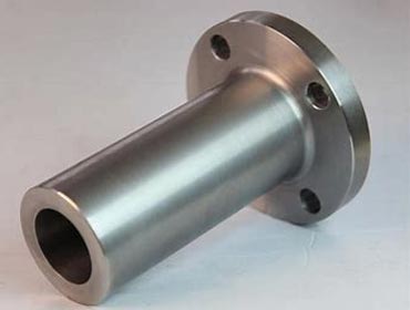
Weld Neck Flanges in hard-to-nd metals. Long Weld Neck Flanges have a hub that extends from the Flanges at the surface, which helps in accommodating the pipe more easily. Alloy Steel Long Weld Neck Flange fall under the group of specialty flanges, reinforcement in services at higher temperatures in the oil industry. A Carbon Steel Long Welding Neck Flanges is preferable in the petroleum and chemical industry as they operate under actuating temperature ranges.
| Dimensions: | ANSI B16.5, ANSI B16.47 Series A & B, MSS SP44, ASA, API-605, AWWA, Custom Drawings |
| Size: | 1/2″ (15 NB) to 48″ (1200NB) |
| Class: | 150 LBS, 300 LBS, 600 LBS, 900 LBS, 1500 LBS, 2500 LBS |
| BS: | BS4504 , BS1560, BS10 , PN6 , PN10 , PN16 , PN25 , PN40, etc |
| Table: | D / E / F / H / J / K |
| Api Standards: | PSI-2000/3000/5000/10000/etc |
| JIS Standards: | 2220-2004 5k/10k/16k, etc |
| Flange Face Type: | Flate Face (FF), Raised Face (RF), Ring Type Joint (RTJ) |
Slip On Flanges
Slip-on Flanges have bored with a diameter slightly larger than the pipe; this helps it to slide\slip over the pipe. This ANSI B16.5 SORF Flange is then welded inside and outside too, with fillet welding. Alloy Steel Slip On Plate Flanges are thinner compared to other ranges, cost-effective and are easy to use in fabricated applications. We supply Carbon Steel Slip-on Raised Face Flanges in both raised face and at faced designs, to industries like agricultural, fertilizers, pharmaceutical, textile and for general engineering purposes

Production Range
| Drilling | |||||||||
|---|---|---|---|---|---|---|---|---|---|
| Nominal Bore | Dia.(D) | Thick.(E) | Dia.(F) | Dia.(B) | Dia.(A) | Height1(H) | Nbr | Holes | Dia.(C) |
| 1/2″ | 90 | 9.6 | 35.05 | 30 | 22.2 | 14 | 4 | 15.87 | 60.3 |
| 3/4″ | 100 | 11.2 | 42.93 | 38 | 27.7 | 14 | 4 | 15.87 | 69.9 |
| 1″ | 110 | 12.7 | 50.80 | 49 | 34.5 | 16 | 4 | 15.87 | 79.4 |
| 1 1/4″ | 115 | 14.3 | 63.50 | 59 | 43.2 | 19 | 4 | 15.87 | 88.9 |
| 1 1/2″ | 125 | 15.9 | 73.15 | 65 | 49.5 | 21 | 4 | 15.87 | 98.4 |
| 2″ | 150 | 17.5 | 91.95 | 78 | 61.9 | 24 | 4 | 19.05 | 120.7 |
| 2 1/2″ | 180 | 20.7 | 104.65 | 90 | 74.6 | 27 | 4 | 19.05 | 139.7 |
| 3″ | 190 | 22.3 | 127.00 | 108 | 90.7 | 29 | 4 | 19.05 | 152.4 |
| 3 1/2″ | 215 | 22.3 | 139.70 | 122 | 103.4 | 30 | 8 | 19.05 | 177.8 |
| 4″ | 230 | 22.3 | 157.22 | 135 | 116.1 | 32 | 8 | 19.05 | 190.5 |
| 5″ | 255 | 22.3 | 185.67 | 164 | 143.8 | 35 | 8 | 22.22 | 215.9 |
| 6″ | 280 | 23.9 | 215.90 | 192 | 170.7 | 38 | 8 | 22.22 | 241.3 |
| 8″ | 345 | 27.0 | 269.75 | 246 | 221.5 | 43 | 8 | 22.22 | 298.5 |
| 10″ | 405 | 28.6 | 323.85 | 305 | 276.2 | 48 | 12 | 25.40 | 362.0 |
| 12″ | 485 | 30.2 | 381.00 | 365 | 327.0 | 54 | 12 | 25.40 | 431.8 |
| 14″ | 535 | 33.4 | 412.75 | 400 | 359.2 | 56 | 12 | 28.57 | 476.3 |
| 16″ | 595 | 35.0 | 469.90 | 457 | 410.5 | 62 | 16 | 28.57 | 539.8 |
| 18″ | 635 | 38.1 | 533.40 | 505 | 461.8 | 67 | 16 | 31.75 | 577.9 |
| 20″ | 700 | 41.3 | 584.20 | 559 | 513.1 | 71 | 20 | 31.75 | 635.0 |
| 24″ | 815 | 46.1 | 692.15 | 663 | 616.0 | 81 | 20 | 34.92 | 74 |
Socket Weld Flanges
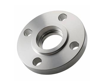
Socket Weld Flanges (SWRF) are counter-bored i.e. the bore of the Flange and pipe, both are same, thereby providing a good ow of the product through the pipe. Initially used for small-sized high-pressure pipes, our SMO 254 Socket Weld Flanges are now used in high-pressure systems too. Our Stainless Steel Socket Weld Flanges are oxidation resistant and promote better weldability and fabricability. We seek to offer ANSI B16.5 Carbon Steel Socket Weld Flanges that have excellent stress corrosion cracking resistance to the LNG, seawater and mining industry.
| Drilling | |||||||||
|---|---|---|---|---|---|---|---|---|---|
| Nominal Bore | Dia.(D) | Thick.(E) | Dia.(F) | Dia.(B) | Dia.(A) | Height1(H) | Nbr | Holes | Dia.(C) |
| 1/2″ | 90 | 11.2 | 35.05 | 30 | 22.2 | 14 | 4 | 15.87 | 60.3 |
| 3/4″ | 100 | 12.7 | 42.92 | 38 | 27.7 | 14 | 4 | 15.87 | 69.9 |
| 1″ | 110 | 14.3 | 50.80 | 49 | 34.5 | 16 | 4 | 15.87 | 79.4 |
| 1 1/4″ | 115 | 15.9 | 63.50 | 59 | 43.2 | 19 | 4 | 15.87 | 88.9 |
| 1 1/2″ | 125 | 17.5 | 73.15 | 65 | 49.5 | 21 | 4 | 15.87 | 98.4 |
| 2″ | 150 | 19.1 | 91.94 | 78 | 61.9 | 24 | 4 | 19.05 | 120.7 |
| 2 1/2″ | 180 | 22.3 | 104.65 | 90 | 74.6 | 27 | 4 | 19.05 | 139.7 |
| 3″ | 190 | 23.9 | 127.00 | 108 | 90.7 | 29 | 4 | 19.05 | 152.4 |
Threaded Flanges
The most noteworthy feature of these changes is that they can be joined to a pipe without welding. The bore of Nickel Threaded Flanges have threads and can be fitted to pipes that have external threads. Stainless Steel Threaded Flanges are low priced, t best for small pipes and can be used in low-pressure applications. They are very beneficial in highly combustible industries where welding is dangerous. We are certified to cater to the challenging requisites of a number of industries through our outstanding products and extraordinary services
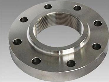
| Drilling | ||||||||
|---|---|---|---|---|---|---|---|---|
| Nominal Bore | Dia.(D) | Thick.(E) | Dia.(F) | Dia.(B) | Height1(H) | Nbr | Holes | Dia.(C) |
| 1/2″ | 90 | 9.6 | 35.05 | 30 | 14 | 4 | 15.87 | 60.3 |
| 3/4″ | 100 | 11.2 | 42.92 | 38 | 14 | 4 | 15.87 | 69.9 |
| 1″ | 110 | 12.7 | 50.80 | 49 | 16 | 4 | 15.87 | 79.4 |
| 1 1/4″ | 115 | 14.3 | 63.50 | 59 | 19 | 4 | 15.87 | 88.9 |
| 1 1/2″ | 125 | 15.9 | 73.15 | 65 | 21 | 4 | 15.87 | 98.4 |
| 2″ | 150 | 17.5 | 91.94 | 78 | 24 | 4 | 19.05 | 120.7 |
| 2 1/2″ | 180 | 20.7 | 104.65 | 90 | 27 | 4 | 19.05 | 139.7 |
| 3″ | 190 | 22.3 | 127.00 | 108 | 29 | 4 | 19.05 | 152.4 |
| 3 1/2″ | 215 | 22.3 | 139.70 | 122 | 30 | 8 | 19.05 | 177.8 |
| 4″ | 230 | 22.3 | 157.22 | 135 | 32 | 8 | 19.05 | 190.5 |
| 5″ | 255 | 22.3 | 185.67 | 164 | 35 | 8 | 22.22 | 215.9 |
| 6″ | 280 | 23.9 | 215.90 | 192 | 38 | 8 | 22.22 | 241.3 |
| 8″ | 345 | 27.0 | 269.75 | 246 | 43 | 8 | 22.22 | 298.5 |
| 10″ | 405 | 28.6 | 323.85 | 305 | 48 | 12 | 25.40 | 362.0 |
| 12″ | 485 | 30.2 | 381.00 | 365 | 54 | 12 | 25.40 | 431.8 |
| 14″ | 535 | 33.4 | 412.75 | 400 | 56 | 12 | 28.57 | 476.3 |
| 16″ | 595 | 35.0 | 469.90 | 457 | 62 | 16 | 28.57 | 539.8 |
| 18″ | 635 | 38.1 | 533.40 | 505 | 67 | 16 | 31.75 | 577.9 |
| 20″ | 700 | 41.3 | 584.20 | 559 | 71 | 20 | 31.75 | 635.0 |
| 24″ | 815 | 46.1 | 692.15 | 663 | 81 | 20 | 34.92 | 749.3 |
Blind Flanges
Commonly referred as blanking flanges, Blind pipe flanges are widely used in high pressure applications. Blind flanges are generally used to seal the end of a piping system to prevent flow of liquids or gases. The use of blind flanges allows ease of access to a piping system once it has been closed. Our blind flanges are available with raised or RTJ faces and also with female threads. Blind flanges can be supplied with or without hub as per the customer requirements. We offer blind plate flanges manufactured at our facility to companies in various industries including shipbuilding, power generation, petrochemical plants, oil refineries, waste water treatment plants, paper mills, pharmaceutical plants and turnkey projects among others.
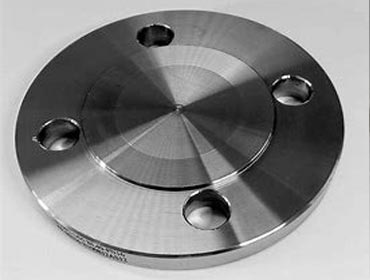
| Drilling | ||||||
|---|---|---|---|---|---|---|
| Nominal Bore | Dia.(D) | Thick.(E) | Dia.(F) | Nbr | Holes | Dia.(C) |
| 1/2″ | 90 | 9.6 | 35.05 | 4 | 15.87 | 60.3 |
| 3/4″ | 100 | 11.2 | 42.93 | 4 | 15.87 | 69.9 |
| 1″ | 110 | 12.7 | 50.80 | 4 | 15.87 | 79.4 |
| 1 1/4″ | 115 | 14.3 | 63.50 | 4 | 15.87 | 88.9 |
| 1 1/2″ | 125 | 15.9 | 73.15 | 4 | 15.87 | 98.4 |
| 2″ | 150 | 17.5 | 91.94 | 4 | 19.50 | 120.7 |
| 2 1/2″ | 180 | 20.7 | 104.63 | 4 | 19.50 | 139.7 |
| 3″ | 190 | 22.3 | 127.00 | 4 | 19.50 | 152.4 |
| 3 1/2″ | 215 | 22.3 | 139.70 | 8 | 19.50 | 177.8 |
| 4″ | 230 | 22.3 | 157.23 | 8 | 19.50 | 190.5 |
| 5″ | 255 | 22.3 | 185.67 | 8 | 22.22 | 215.9 |
| 6″ | 280 | 23.9 | 215.90 | 8 | 22.22 | 241.3 |
| 8″ | 345 | 27.0 | 269.75 | 8 | 22.22 | 298.5 |
| 10″ | 405 | 28.6 | 325.85 | 12 | 25.4 | 362.0 |
| 12″ | 485 | 30.2 | 381.00 | 12 | 25.4 | 431.8 |
| 14″ | 535 | 33.4 | 412.75 | 12 | 28.57 | 476.3 |
| 16″ | 595 | 35.0 | 469.90 | 16 | 28.57 | 539.8 |
| 18″ | 635 | 38.1 | 533.40 | 16 | 31.75 | 577.9 |
| 20″ | 700 | 41.3 | 584.20 | 20 | 31.75 | 635.0 |
| 24″ | 815 | 46.1 | 692.15 | 20 | 34.92 | 749.3 |
Lap Flanges
Lap Flanges are used with a stub end, which is welded to the pipe. Alloy Steel Lapped Flanges are designed in a way that they swing over the pipe without the need to be welded. As they do not come in contact with the inner fluid, they do not corrode and can be re-used. Our ANSI B16.5 Stainless Steel Flanges are inexpensive and widely useful. In addition, they can be easily assembled and dismantled for a quick inspection
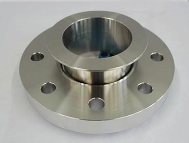
| Drilling | ||||||||
|---|---|---|---|---|---|---|---|---|
| Nominal Bore | Dia.(D) | Thick.(E) | Dia.(B) | Dia.(A) | Height(H) | Nbr | Holes | Dia.(C) |
| 1/2″ | 90 | 11.2 | 30 | 22.9 | 16 | 4 | 15.87 | 60.3 |
| 3/4″ | 100 | 12.7 | 38 | 28.2 | 16 | 4 | 15.87 | 69.9 |
| 1″ | 110 | 14.3 | 49 | 34.9 | 17 | 4 | 15.87 | 79.4 |
| 1 1/4″ | 115 | 15.9 | 59 | 43.7 | 21 | 4 | 15.87 | 88.9 |
| 1 1/2″ | 125 | 17.5 | 65 | 50.0 | 22 | 4 | 15.87 | 98.4 |
| 2″ | 150 | 20.7 | 78 | 62.5 | 25 | 4 | 19.05 | 120.7 |
| 2 1/2″ | 180 | 22.3 | 90 | 75.4 | 29 | 4 | 19.05 | 139.7 |
| 3″ | 190 | 23.9 | 108 | 91.4 | 30 | 4 | 19.05 | 152.4 |
| 3 1/2″ | 215 | 23.9 | 122 | 104.1 | 32 | 8 | 19.05 | 177.8 |
| 4″ | 230 | 23.9 | 135 | 116.8 | 33 | 8 | 19.05 | 190.5 |
| 5″ | 255 | 23.9 | 164 | 144.4 | 36 | 8 | 22.22 | 215.9 |
| 6″ | 280 | 25.4 | 192 | 171.4 | 40 | 8 | 22.22 | 241.3 |
| 8″ | 345 | 28.6 | 246 | 222.2 | 44 | 8 | 22.22 | 298.5 |
| 10″ | 405 | 30.2 | 305 | 277.4 | 49 | 12 | 25.40 | 362.0 |
| 12″ | 485 | 31.8 | 365 | 328.2 | 56 | 12 | 25.40 | 431.8 |
| 14″ | 535 | 35.0 | 400 | 360.2 | 79 | 12 | 28.57 | 476.3 |
| 16″ | 595 | 36.6 | 457 | 411.2 | 87 | 16 | 28.57 | 539.8 |
| 18″ | 635 | 39.7 | 505 | 462.3 | 97 | 16 | 31.75 | 577.9 |
| 20″ | 700 | 42.9 | 559 | 514.4 | 103 | 20 | 31.75 | 635.0 |
| 24″ | 815 | 47.7 | 663 | 616.0 | 111 | 20 | 34.92 | 749.3 |
Plate Flanges
We are a manufacturer, supplier and exporter of Plate Flanges, which are accepted by major industries as a cost-efficient alternative to other types of flanges whose cost increases due to its expensive production pattern. Manufactured with procedures that are compliant with global flange standards, our Stainless Steel Plate Flanges are free from any cracks and deformities, due to which they last longer and provide an extended service lifespan. Our Carbon Steel Plate special maintenance needs,and added advantage to use them. We supply these ANSI B16.5 Plate Flanges to the irrigation industry.
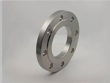
Production Range
| Dimensions: | ANSI B16.5, ANSI B16.47 Series A & B, MSS SP44, ASA, API-605, AWWA, Custom Drawings |
| Size: | 1/2″ (15 NB) to 48″ (1200NB) |
| Class: | 150 LBS, 300 LBS, 600 LBS, 900 LBS, 1500 LBS, 2500 LBS |
| BS: | BS4504 , BS4504, BS1560, BS10 , PN6 , PN10 , PN16 , PN25 , PN40, etc |
| Table: | D / E / F / H / J / K |
| Api Standards: | PSI-2000/3000/5000/10000/etc |
| JIS Standards: | 2220-2004 5k/10k/16k, etc |
| Flange Face Type: | Flate Face (FF), Raised Face (RF), Ring Type Joint (RTJ) |
Orifice Flanges
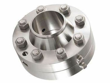
Orifice Flanges are used with orifice meters for the purpose of measuring the flow rate of either liquids or gases in the respective pipeline. Pairs of pressure "Tappings", mostly on 2 sides, directly opposite each other, are machined into the orifice flange. This makes separate orifice carriers or tappings in the pipe wall unnecessary. Orifice Flanges generally come with either Raised Faces or RTJ (Ring Type Joint) facings. They are, for all intensive purposes, the same as weld neck and slip on flanges with extra machining. The image on the right shows a set Orifice Flanges, where a Orifice Plate is mounted and a jack screw is machined. This jack screw is used to facilitate separating the flanges for inspection or replacement of the Orifice Plate and gaskets. The range of orifice flanges covers all standard sizes and ranges, and all common flange materials. Flanges are available in Welding Neck, Slip On, and Threaded form, and are typically supplied with two 1/2" NPT tappings in each flange.
Spectacle Blind Flange
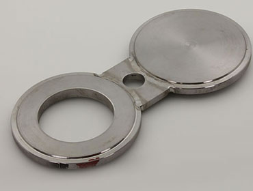
These Spectacle Blind Flange are manufacture in different Material of Flanges like SORF Flanges, Carbon Steel Spectacle Blind Flange, Stainless Steel Spectacle Blind Flange, Alloy Steel Spectacle Blind Flange, Duplex Steel Spectacle Blind Flange, Inconel Spectacle Blind Flange, Monel Spectacle Blind Flange, Hastelloy Spectacle Blind Flange, Copper Nickel Spectacle Blind Flange in India & Asia, conform to Slip On specifications. A spectacle blind is a safety device used to isolate a section of line or piece of equipment when the line or equipment needs to be inspected or removed from service. It is different than a valve in that the blind is a permanent or long term isolation device. A spectacle blind is machined from a single piece of metal that is cut to match the pipe size, fit between two pipe flanges and requires an additional gasket when it is installed.
| NPS | OutsideA | InsideB | CenterlineC | Thicknesst | Web WidthW |
| 1/2 | 45 | 16 | 60 | 3 | 38 |
| 3/4 | 54 | 21 | 70 | 3 | 38 |
| 1 | 64 | 27 | 80 | 3 | 38 |
| 1¼ | 73 | 42 | 90 | 6.4 | 38 |
| 1½ | 83 | 48 | 100 | 6.4 | 38 |
| 2 | 102 | 61 | 120 | 6.4 | 51 |
| 2½ | 107 | 73 | 140 | 6.4 | 51 |
| 3 | 133 | 89 | 150 | 6.4 | 64 |
| 3½ | 159 | 102 | 175 | 9.7 | 64 |
| 4 | 172 | 114 | 190 | 9.7 | 64 |
| 5 | 194 | 141 | 215 | 9.7 | 76 |
| 6 | 219 | 168 | 240 | 12.7 | 76 |
| 8 | 276 | 219 | 300 | 12.7 | 76 |
| 10 | 337 | 273 | 360 | 15.7 | 102 |
| 12 | 406 | 324 | 430 | 19.1 | 102 |
| 14 | 448 | 356 | 475 | 19.1 | 108 |
| 16 | 511 | 406 | 460 | 22.4 | 108 |
| 18 | 546 | 457 | 580 | 25.4 | 114 |
| 20 | 603 | 508 | 635 | 28.4 | 121 |
| 24 | 714 | 610 | 750 | 31.8 | 140 |
| NPS | OutsideA | InsideB | CenterlineC | Thicknesst | Web WidthW |